StageCore1
Binaries (FPGA configuration, operating system and firmware) targeting a Xilinx Spartan-6
(XC6SLX25-2FTG256C) FPGA. The system has a versatile licensing mechanism for all software
and hardware modules. This mechanism allows for cost-efficient and application-oriented use
of options and features.
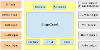
The core can be used in any custom FPGA-System that complies to the component and pinout
specification. The included firmware is based on a modular library design to be used in
different scenarios. Hardware and pin configuration are stored in a configuration EEPROM,
hardware and firmware features are enabled through the license file located along with the
FPGA configuration and the firmware binaries in the system ROM.
Downloads
Management and Update Tool (NetView) - Java program located inside the zip file.
Firmware Bundle
System Features
User provided device name and icon for easy identification, unique unit ID.
User reset, sets defaults for common parameters such as networking for easy retrieval
in case of misconfiguration.
Monitor dialog through 115kBaud UART and Telnet.
Powerful configuration parameter dictionary.
LwIP 1.4.1 with Ethernet and SLIP drivers, performant multithreading architecture.
System profiler.
Embedded System Administration (ESA) server.
Single file bundle (zip archive) for distribution.
IDN Server Module
Sophisticated timeline reassembly and tracking algorithm with jitter compensation and
automatic latency adaption.
Fast and efficient zero-copy network buffer management.
Server implementation derived from object oriented and device independent IDN library.
Detailed packet statistics.
IDN Bridge Module
Plug and play. Automatic setup and teardown of bridges through network probes.
Ability to scan the network for compatible receivers, store the list in nonvolatile memory
and build bridges. The scan works for directly connected devices or across switches.
Supports configured, self initiated bridges and externally initiated bridges to be used
with monitors and recorders.
Receiver configuration through UnitID and IP-Address to support dynamic address
assignments and static assignments behind routers.
ISP signal splitter, support for 2 further receivers (total of 3) for signal duplication or
multiplication (more in preparation).
Additional drain for remote host initiated brides for monitoring or recording.
Laser Projector Output Core
Single head and dual head operation with independent timing.
Flexible frequency synthesizer with a resolution of 250nS. The synthesizer allows for
precise playback frequency match and detune needed by latency adaption.
Timeshifts for intensity and color (based on galvo command, known as colorshift) and
color lines (based on intensity, introduced as color line tweaking).
Timeshifts between signals are configured in units of microseconds with a resolution of
250 nanoseconds. This keeps the shifts stable for all sample frequencies.
DAC output calibration (gain and offset).
Maximum throughput of 250.000 samples per second, full resolution, all channels.
DMX512 Output Core
Byte stream implementation allows for arbitrary start codes or stray custom data
mixed with DMX512 data.
Large hardware FIFO reduces CPU attendance.
Commands for idle (all one) and break (all zero) characters.
ISP (ILDA Standard Projector) Input Core
Fully implemented ISP-Port (X, Y, I, R, G, B, U1, U2, U3, U4, Shutter, Interlock).
Interlock check through oscillator and edge detection.
Calibration for all inputs (offset and gain) in hardware.
DMX512 Input Core
Ethernet Core
FPGA Signals
Basic core and CPU signals
| CLK25 | T8 | 25 MHz system clock, ± 25ppm |
| UART_LOG_TX | C8 | Console log (115 kBaud, 8Bit, 1Stop, no parity). StageCore1 uses this UART to send runtime log messages. |
| UART_MON_RX | A9 | User monitor dialog (115 kBaud, 8Bit, 1Stop, no parity) |
| UART_MON_TX | C9 | User monitor dialog (115 kBaud, 8Bit, 1Stop, no parity) |
| DLED<0> | E4 | Boot error code LED (red, high = on, low = off) |
| DLED<1> | F5 | Boot error code LED (red, high = on, low = off) |
| DLED<2> | N4 | Boot error code LED (red, high = on, low = off) |
| DLED<3> | B3 | Boot error code LED (red, high = on, low = off) |
| TEST<0> | N9 | CPU test pin (optional) |
| TEST<1> | P9 | CPU test pin (optional) |
| TEST<2> | R9 | CPU test pin (optional) |
| TEST<3> | T9 | CPU test pin (optional) |
| TEST<4> | M9 | CPU test pin (optional) |
| TEST<5> | N8 | CPU test pin (optional) |
QSPI Flash ROM (8MB, Winbond W25Q64FVSSIG or compatible)
| QSPI_CLK | R11 | Clock |
| QSPI_CS | T3 | Chip select |
| QSPI_IO0 | T10 | DI (IO0) |
| QSPI_IO1 | P10 | DO (IO1) |
| QSPI_IO2 | N12 | /WP (IO2) |
| QSPI_IO3 | P12 | /HOLD (IO3) |
RMII PHY (Micrel KSZ8021RNL or compatible)
| RMII_CLK | L13 | RMII clock output |
| RMII_RXD<0> | T13 | Receive data input [0] |
| RMII_RXD<1> | R12 | Receive data input [1] |
| RMII_RX_ER | H11 | Receive error input |
| RMII_CRS_DV | F12 | Carrier sense / Receive data valid input |
| RMII_TXD<0> | H13 | Transmit data output [0] |
| RMII_TXD<1> | H14 | Transmit data output [1] |
| RMII_TX_EN | E12 | Transmit enable output |
| MII_MDC | T12 | Management interface (MII) clock output |
| MII_MDIO | L12 | Management interface (MII) data I/O |
| ETH_PHY_RST_N | G11 | PHY reset output, active low, needs external 4k7 pulldown |
| ETH_PHY_IRQ_N | E13 | PHY interrupt input, active low |
| ETH_PEER_LED | P11 | Peer LED (low = on, Z = off) |
System status
| READY | M6 | System ready condition (everything up and running). Can be used in a condition to open an interlock. |
| ERROR_LED | T14 | Error LED (red, low = on, Z = off) |
| SESSION_LED | L14 | Session LED (blue, low = on, Z = off), this LED is controlled by the IDN server and signals an active session. |
| BRIDGE_LED | L16 | Bridge LED (blue, low = on, Z = off), this LED is controlled by the feed client and signals an active bridge. |
| MATE_STATUS1_LED | P15 | Mate status LED (green, low = on, Z = off) |
| MATE_STATUS2_LED | P16 | Mate status LED (green, low = on, Z = off) |
| FEED_STATUS1_LED | R14 | Feed status LED (green, low = on, Z = off) |
| FEED_STATUS2_LED | T15 | Feed status LED (green, low = on, Z = off) |
| PUSH_BUTTON | T7 | Push button used for communication/firmware reset and pairing |
I²C
A 24C64 type EEPROM (or compatible) shall be reachable at address 0xA8
| IIC_SCL | P4 | Needs external pullup |
| IIC_SDA | T4 | Needs external pullup |
Laser projector: Common converter signals
| CV_CLK1 | C10 | DAC clock output (galvo, laser, color) |
| CV_CLK2 | C4 | 16 Bit ADC clock output |
| CV_CLK3 | F7 | 12 Bit ADC clock output |
Laser projector: Galvo commands and feedback
Converters used: AD5662xRJ-2 or compatible
| G1C_CS | B5 | Port 1 galvo chip select output |
| G1CX_D | A5 | Port 1 galvo X output (ISP out: X) |
| G1CY_D | B6 | Port 1 galvo Y output (ISP out: Y) |
| G2C_CS | H15 | Port 2 galvo chip select output |
| G2CX_D | H16 | Port 2 galvo X output (ISP out: U4) |
| G2CY_D | J14 | Port 2 galvo Y output |
Laser projector: Laser commands and feedback
The timing of these signals is referenced to the galvo signals (Blankshift). Converters used: DAC7311IDCK or compatible
| L1_CLR | D6 | Port 1 laser clear output (ISP out: Shutter). This signal indicates the intention of laser emission (low = dark, high = emission). |
| L1C_CS | C6 | Port 1 chip select output |
| L1C_D | B10 | Port 1 data output (ISP out: Intensity) |
| L2_CLR | B14 | Port 2 laser clear output. This signal indicates the intention of laser emission (low = dark, high = emission). |
| L2C_CS | A14 | Port 2 chip select output |
| L2C_D | D11 | Port 2 data output |
Laser projector: Color line commands
The timing of these signals is referenced to the laser control signals and can be individually tweaked. Converters used: DAC7311IDCK or compatible
| A1_CS | C7 | Port 1 line A chip select output |
| A1_D | A7 | Port 1 line A data output (ISP out: R) |
| B1_CS | D5 | Port 1 line B chip select output |
| B1_D | C5 | Port 1 line B data output (ISP out: G) |
| C1_CS | F9 | Port 1 line C chip select output |
| C1_D | D9 | Port 1 line C data output (ISP out: B) |
| D1_CS | E7 | Port 1 line D chip select output |
| D1_D | E8 | Port 1 line D data output |
| A2_CS | F13 | Port 2 line A chip select output |
| A2_D | F14 | Port 2 line A data output (ISP out: U1) |
| B2_CS | G14 | Port 2 line B chip select output |
| B2_D | G16 | Port 2 line B data output (ISP out: U2) |
| C2_CS | J13 | Port 2 line C chip select output |
| C2_D | K14 | Port 2 line C data output (ISP out: U3) |
| D2_CS | J11 | Port 2 line D chip select output |
| D2_D | J12 | Port 2 line D data output |
Laser projector: Other signals
| ISP_DMX_OUT | P5 | DMX512 output according to ISP-DMX standard |
Laser projector: ILDA Standard Projector (ISP) input
Converters used: ADS8326(16 Bit) and ADS7866(12 Bit) or compatible
| ISP_CS16 | D14 | 16 bit converter chip select output |
| ISP_CS12 | D11 | 12 bit converter chip select output |
| ISP_X | D12 | X converter data input (16 Bit) |
| ISP_Y | A14 | Y converter data input (16 Bit) |
| ISP_I | L10 | I converter data input (12 Bit) |
| ISP_R | M15 | R converter data input (12 Bit) |
| ISP_G | M10 | G converter data input (12 Bit) |
| ISP_B | M16 | B converter data input (12 Bit) |
| ISP_U1 | E6 | U1 converter data input (12 Bit) |
| ISP_U2 | A4 | U2 converter data input (12 Bit) |
| ISP_U3 | N5 | U3 converter data input (12 Bit) |
| ISP_U4 | D8 | U4 converter data input (16 Bit) |
| ISP_CLR | B14 | Shutter input |
| ISP_ITX | E15 | Interlock transmit output |
| ISP_IRX | E16 | Interlock receive output |
| ISP_DMX_IN | T5 | DMX512 input according to ISP-DMX standard |
|


